What is Scatter file? What is the use and how to use
I am not sure i can learn everything about scatter file here, but let me try to explain what i have understood. Same project used in post 3 is used.
Here is the plan:
- First we will compile the Keil project and make sure there are no errors.
- Then we will find out where is the scatter file located.
- then we will try to understand what it is doing.
- Then we will go to the arm linker guide, only take a picture of common syntax of scatter file and come back here. The linker guide of ARM is like 865 pages!!
- Now it gets interesting. We will tell Keil not to use default Scatter file but our own. Yes, we will create our own. why not our own? right?
- Then if there are no errors, we will proceed to play around moving different parts of the object file (RW, ZI etc) into locations we wish to.
- Too much promises i have made.. i am getting scared already :(
Step 1: Compile project to make sure there are no errors
Compile and build the project. Build output window should show no errors. Easy step this was.
 |
| Successfully Compiled Project - No errors |
Step 2: Find the location of Scatter file in the Keil Project Location
Scatter file has *.sct extension. Quickly you can search for the file in the project folder. For the current project under discussion, the file was located in the folder named "Objects". Have a look.
 |
| Location of Scatter file in Keil |
Step 3: What is this Scatter file doing anyway?
Let us open and see the file. What to lose?
Ehh? There was nothing much in the file. it looked simple. I could understand few things ( i hope so).
 |
| Scatter file looks like this in Keil - default generated one |
Here are the few things i can understand from the above file:
- *.o means any object file ( in our example it can be project.o, project2.o etc etc etc)
- RO means Read Only Sections
- RW and ZI also we know
- 0x08000000 is the start address of Flash Memory in STM32L476 MCU ( See Pic Below)
- 0x00100000 corresponds to 1 MegaByte of memory location, which is true for the STM32 Nucleo board we have. So, our execution region will be from 0x08000000 and can be upto 0x08100000.
- RAM is where variables are placed during code execution. RW_IRAM1 is just a label, 0x2000000 is the location where the RAM region starts. The RAM in STM32L467RG which is on this particular Nucleo board is 128 KBytes (0x20000)
- The scatter file stops the RAM at 0x18000. I know why, i think. it is because, it has kept 512 (0x200) bytes of memory to Stack i guess. That i had seen in start up file. We will see the startup file too in detail but for the moment, let us focus only on the scatter file.
 |
| Right Side there is 0x0800 0000 and maximum allocated is 1 MB (0x0010 0000) |
Step 4: Scatter file Syntax from ARM linker file
I access the Linker guide pdf file from here (see below pic). The file can be always downloaded from the website too.
 |
| accessing Linker Guide in Keil application |
Below is the snapshot of scatter file from the guide. it is official :)
 |
| Scatter file syntax defined in ARM Linker Guide |
Step 5: Creating our own scatter File
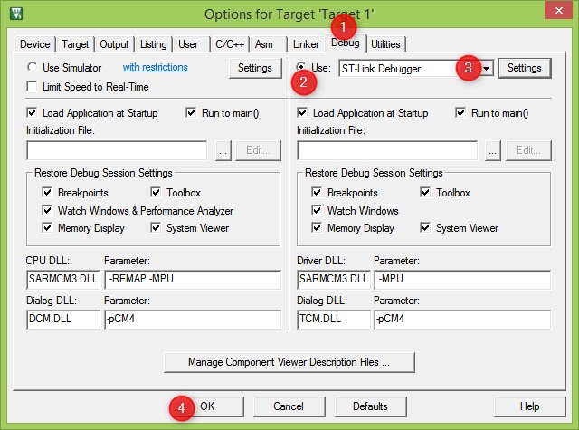
Now it is interesting for me. We will tell Keil to use our own Scatter file. But how to tell? in the pic below, i had this as the settings in Linker options under project option menu.
Go to Projects in Menu bar -> Options for Target -> and select Linker tab in the options window.
- Deselect the option "Use Memory Layout from Target Dialog".
- Just copy paste the existing scatter file to the file name below shown in image and save. you can also delete the original one. let it go :)
 |
| Linker option in Keil-scatter file |
We will create a copy of the existing scatter file and rename it to FirstProj_Edit.sct in the objects folder. hope you remember where to find it.
let us start! ( already started right? :) )
 |
| i have made magic and replaced the default scatter file with my own. contents are same |
Step back!
a little look again after deselecting the option "Use Memory Layout from Target Dialog", we take okay?
 |
| Linker tab window in Keil. see the RAM (R/W) and ROM(R/O) addresses. so easy to change to whatever we want, it seems. |
Make sure all four points highlighted in the image matches with your linker tab too. because, it is needed soon. We will next play with our scatter file and do some changes and study, so as to really call, we have our own scatter file... not just renamed scatter file.. what do you say?
Compile once again.
Also go to the folder and see that no scatter file is there except ours. We are creating our own. Why to make Keil suffer. let us help it.
We are ready to dig little deeper into Scatter file. Breathe in. Jump!
Step 6: Customizing Scatter file in Keil - let us begin. Last step, big step, still baby step :)
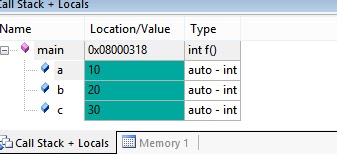
Next two images are very simple, saying nothing other than the memory location of ZI variables, RW variable and a location of a function. There were two source files right? so i am tracking addresses of variables in both source files. There is only option to monitor address of only 4 variables at a time. so i have taken screenshots twice. once for source file protect.c and another for file project2.c. Let us see how scatter file can control who goes where later.
For now, a little peek into the current memory addresses of variables with our just born scatter file :)
 |
| Memory addresses of three variables in source file project.c |
Here it is. from the above pic, address of variable array3 is 0x200003C0 (note that they have taken 8 bytes as they were defined as long long int), it was not necessary, but i declared it as long long int. that is fine. The address of variable array is 0x20000000 ( start address of RAM!!!). Finally, address of arra2 variable is 0x20000030. Don't hate me for meaningless variable names.
May be in one blog post we can talk about nice nice names for variables.
Let us see the second source file info too. what has it done to you? let us treat both equally.
 |
| Memory addresses of variables in source file project2.c |
The addresses of variables in second file we can see in the image right? i am not typing again. I am not Lazy but i am in energy save mode :)
Here is the essence of these. The variables have taken locations as they wish. If i am the programmer, and i do not have any problem with memory allocation of the variable by Keil default scatter file and linker, it is okay. but there are n number of use cases where you have to keep things in order. I do not know much use cases but a few are
- saving important variables in memory area where you can protect
- memory area shared by multiple resources
- memory area in flash where you like to monitor the value using third party tool etc.
Now the game
Observe the difference between two images. Both are contents of our scatter file only. first image is as is right after renaming it. Second one i have modified Small things only. Find out the differences.
 |
| Keil original scatter file. We have only renamed it. Great thing! |
 |
| Scatter file after doing small changes |
okay. Here are the changes i have done in our custom scatter file ( sounds like a pro)
- I have declared one more section by name RW_IRAM2 (it can be anything, just followed existing name convention)
- Removed the +ZI from first section of the RW data which is RW_IRAM2
- The RAM memory why to waste ya? so stopped at 0x1000 size. that is more than enough for our great project which has no purpose :) Just kidding. One day we will send our project to moon. for now, loosen up the buckle. :)
- Basically we have divided the RAM into two sections. one section starts from 0x20000000 and is of size 0x1000, the second section of RAM starts from 0x20001000 (obviously right?) and is of small size of 0x100
- First RAM section, contains only RW data ( don"t ask me now, what is RW data? ask it is okay)
- Second RAM section holds the ZI data
Sounds cool right? but does it work? ya it should. why not? let us compile the code and monitor the memory locations again.
Below image shows the new memory addresses of variables in source file project.c. is not it cool to see the locations same as how we define it. feels like i am controlling the whole world.
 |
| New memory addresses due to custom Scatter file for source file project.c |
 |
| new memory addresses in project2.c file due to custom scatter file |
at this point, i want to slow down a little. Was i fast anywhere, by the way? nope :)
Let us look at the new scatter file.
 |
| A little modified scatter file - another view |
Scatter file is like guideline for the linker. Like a rule book. Linker abides by the rule of the scatter file.
You can lie too. You can tell, your RAM address starts from 0x10000000 and it will believe. It maps all your variables (RW data, ZI data, for example) to that location. You flash your hex code. When it boots, the startup code tries to access the illegal location and fails doing nothing.
What I wanted to tell is that scatter file is blindly followed by linker. SO, have to be very careful while handling scatter file, and objects and variables in it.
So, here it is. Linker sees our scatter file.
Now linker has many files and the objects to handle. Our source files are two. there is one startup file (which we will learn for sure, Pakka, line to line) and other library files.
So, linker has to manage things other than our two project.c and project2.c files.
First, the linker gets all the RO sections from all the objects and put it in the ER_IROM1 section.
*.o means all the object files (project.o, project2.o, any_other_source_file.o)
I do not know what is (InRoot$$Sections). We shall update it when we understand.
Next comes two RAM sections (RW_IRAM1 and RW_IRAM2).
RW_IRAM1 section gets all the RW contents from all object files. RW contents will be filled with non zero initialized global variables
RW_IRAM2 section gets ZI data on same lines from all the object files.
Linker does it all. Does all the mapping of different sections into different defined regions in scatter file.
Here are the images showing memory addresses of two source files
 |
| new memory addresses due to Scatter file |
 |
| New memory addresses due to new Scatter file |
The variable arrayp2 is the only uninitialized global variable which qualifies for ZI data among our two source files.
So, it is mapped to the address 0x20001000, which was instructed to linker in the scatter file of ours.
The array variable is mapped to address 0x20000000 as it is the first RW variable type. So, i encourage you to try different address values, different sized values and try to see what happens.
We can assign only 100 bytes for ZI data and declare a 200 byte zero initialized global array. Then Linker will not be able to place our variable of 200 byte size in 100 byte location. it will give an error.
It will be fun to try.
This post is getting lengthy than assumed.
Still, I am glad you are still here, following.
One last experiment. We will dive little deeper. I promise, after this we will surface up for air to swim out. Too much cold here.
Let us again open our custom scatter file in a text editor. The new modified scatter file looks like this.
 |
| new customized scatter file |
Here is what i am trying to accomplish in the new scatter file.
- I want to locate objects of individual source files in distinct locations
- RW data of project2.o will be placed at 0x20000000 --RW_IRAM1
- ZI data of project2.o will be placed at 0x20000100 --RW_IRAM2
- ZI data of project.o will be placed at 0x20000200 --RW_IRAM3
- RW data of project.o will be placed at 0x20000300 --RW_IRAM4
6. RW_IRAM5 section is for startup file and other configuration files of MCU which we still not have touched upon.
So, save the scatter file. Re compile and re build the project.
Now it is time to check the memory addresses of variables again. If we have declared sections in scatter file properly, we should be able to see the changes in memory addresses.
I have done one small change in the code. i have added one variable array4 in project.c file. This is to get one ZI data in the picture. Please don't mind.
 |
| Project.c file and addresses of its variables |
 |
| project2.c file and new addresses of its variables |
Now, new addresses of all variables we can monitor, to see that it matches the addresses as defined in the scatter file.
0x20000000 - array3p2 (First RW data in project2.c)
0x20000100 - arrayp2 (First ZI data in project2.c)
0x20000200 - array4 (First ZI data in project.c)
0x20000300 - array (First RW data in project.c)
In coming posts I want to learn the location in scatter file which we have not dared to touch. the RO location. What is at address 0x08000000 and more.
Also, how about placing each and every variable in the location we want. This is over acting only, but they have their own use cases. Let us wait and see more in 1000ARMS in coming days.
Have Fun Scattering!
--
This a post which is a part of mission 1000 ARMs which is to empower the author to be able to write 1000 ARM programs. 1000 ARMs programs is not really guaranteed but a good learning for sure.


